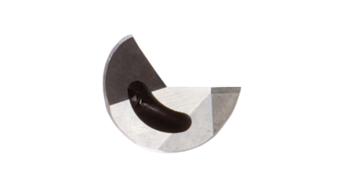
Kidney Hole - Up to 7.00mm diameter
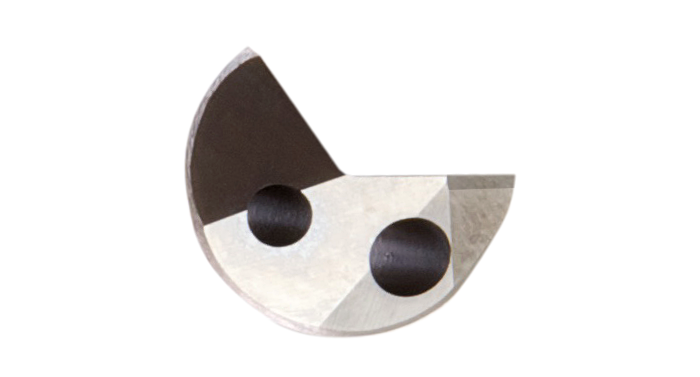
Twin Hole - Over 7.00mm diameter
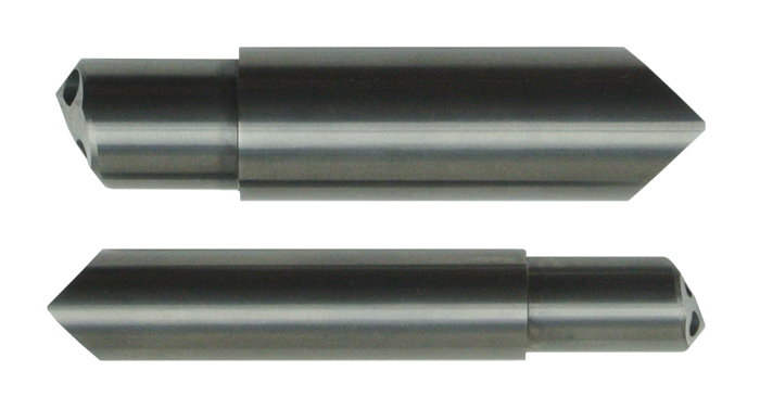
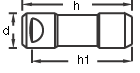
Step Drills, please supply drawing as per requirement
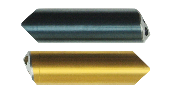
Coated Tips, TiN & TiAlN available
Hammond & Company Ltd
Finway Road
Hemel Hempstead
Hertfordshire
HP2 7PT
United Kingdom
Tel +44 (0)1442 212211
Fax +44 (0)1442 252003
Email info@hammco.com
Finway Road
Hemel Hempstead
Hertfordshire
HP2 7PT
United Kingdom
Tel +44 (0)1442 212211
Fax +44 (0)1442 252003
Email info@hammco.com
- Gundrill Design
- Manufacturing Spec.
- Cutting Geometry
- Cutting Parameters
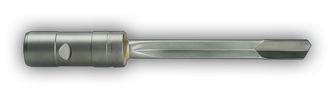
Before drilling commences the gun drill must be suported by a guide bush or pre-drilled start hole. Coolant is delivered directly to the cutting edges through the hollow shank and the chips are evacuated back along the V configuration of the tip and shank.
The periphery of the cutting tip is contoured in such a way as to provide both support pads and lubrication galleries. The forces generated by the single sided cutting action act directly on the support pads creating a burnished surface finish and size control down to IT7 tolerances.
Gun drill tips can be manufactured with a step that has either a cutting, or non cutting pilot. Coated tips are also available upon request. These may have a TiN (Titanium Nitride) coating, or a TiAlN (Titanium Aluminium Nitride) coating.
A regrinding service is available at our Hemel Hempstead factory for gun drills, Ventec drills and Speedfeed drills.
Hardened steel guide bushes and whip guides are available for purchase. See accessories. accessories.
| Driver Design | Ref | d | h | h1 |
|---|---|---|---|---|
HAMMOND STANDARD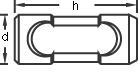 |
CA | 16 | 40 | |
| CB | 25 | 50 | ||
| CC | 35 | 60 | ||
AMERICAN STANDARD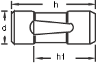 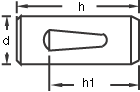 |
AA | 1/2" | 38 | 26 |
| DM | 3/4" | 70 | 46 | |
| AC | 1.00" | 70 | 55 | |
| AD | 1.25" | 70 | 55 | |
| AE | 1.50" | 70 | 55 | |
|
EUROPEAN STANDARD 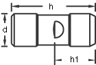
|
AF | 10 | 40 | 24 |
| AK | 16 | 45 | 31 | |
| AG | 20 | 70 | 34 | |
| AH | 25 | 70 | 34 | |
AJ |
32 |
70 |
34 |
| Driver Design | Ref | d | h | h1 | |
|---|---|---|---|---|---|
 |
AN | 16 | 50 | 47 | |
WELDON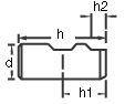 |
BF | 16 | 48 | 24 | |
| h2 | BG | 20 | 50 | 25 | |
| 17 | BH | 25 | 56 | 32 | |
| 19 | BJ | 32 | 60 | 36 | |
19 |
BK | 40 | 70 | 40 | |
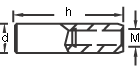 |
DG | 10 | 60 | M6X0.5 | |
| DH | 16 | 80 | M10X1.0 | ||
| DK | 25 | 100 | M16X1.5 | ||
| DL | 36 | 120 | M25X1.5 | ||
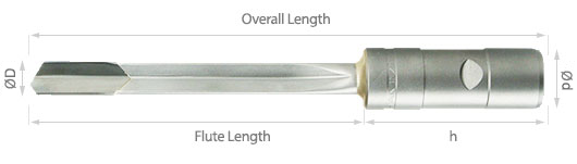
Ordering Information
When ordering Gun Drills please state diameter, overall length, driver design and, where possible, the material to be cut. There are numerous cutting geometries available for the Gun Drills carbide tip.
Alternatively, go towards the end of this website and order by Product Codes.
Product Codes.
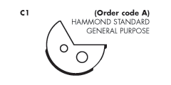
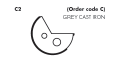
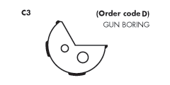
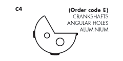
Cutting Head Contours
 |
|
 |
 |
Tubular Shank DimensionsHammond gundrill shanks are manufactured from high quality chrome molybdenum steel and are designed to achieve maximum coolant flow, chip clearance and torsional rigidity. |
|||||
 | |||||
| Ø Range | Ø Tube | Ø D Range | Ø Tube | Ø D Range | Ø Tube |
|---|---|---|---|---|---|
| 3,00-3,14 | 2,8 | 6,50-6,99 | 6,2 | 13,90-14,89 | 13,4 |
| 3,15-3,39 | 2,95 | 7,00-7,29 | 6,7 | 14,90-15,89 | 14,4 |
| 3,40-3,64 | 3,2 | 7,30-7,59 | 7,0 | 15,90-16,89 | 15,3 |
| 3,65-3,87 | 3,45 | 7,60-7,94 | 7,3 | 16,90-17,89 | 16,2 |
| 3,88-3,99 | 3,65 | 7,95-8,34 | 7,6 | 17,90-18,89 | 17,2 |
| 4,00-4,19 | 3,8 | 8,35-8,54 | 8,0 | 18,90-19,89 | 18,2 |
| 4,20-4,44 | 4,0 | 8,55-8,94 | 8,2 | 19,90-20,89 | 19,2 |
| 4,45-4,74 | 4,25 | 8,95-9,34 | 8,6 | 20,90-21,89 | 20,2 |
| 4,75-4,97 | 4,55 | 9,35-9,94 | 9,0 | 21,90-22,89 | 21,2 |
| 4,98-5,24 | 4,75 | 9,95-10,64 | 9,6 | 22,90-23,89 | 22,2 |
| 5,25-5,49 | 5,0 | 10,65-10,94 | 10,3 | 23,90-24,89 | 23,2 |
| 5,50-5,74 | 5,25 | 10,95-11,94 | 10,6 | 24,90-26,89 | 24,2 |
| 5,75-5,94 | 5,5 | 11,95-12,54 | 11,6 | 26,90-28,89 | 26,2 |
| 5,95-6,29 | 5,7 | 12,55-12,94 | 12,2 | 28,90-30,89 | 28,2 |
| 6,30-6,49 | 6,0 | 12,95-13,89 | 12,6 | 30,90-33,00 | 30,2 |
| Updated August 2013 | |||||
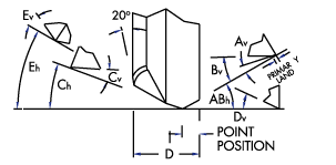
Hammond Recommended Geometry for Various Materials
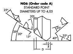
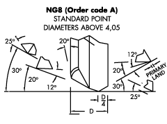
| Drill Diameter. | Primary Land | Chamfer at 20° | Ø 3,0 to 12,0 | 0,4 – 0,6 | 0,4 – 0,6 |
|---|---|---|
| Ø 12,0 to 25,0 | 0,6 – 0,8 | 0,6 – 0,8 |
| Ø 25,0 to 32,0 | 0,8 – 1,2 | 0,8 – 1,2 |
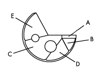
| Facet Description |
NG4 Aluminium (Order code B) |
NG13 Grey Cast Iron (Order code E) |
NG80 Flat Bottom (Order code G) |
||||
|---|---|---|---|---|---|---|---|
| Horiz. | Vertical | Horiz. | Vertical | Horiz. | Vertical | ||
| A | Outer Primary | +15° | +15° | +40° | +12° | +1° | +12° |
| B | Outer Secondary | +14,5° | +20° | +39,5° | +25° | +1° | +20° |
| C | Inner Relief | -20° | +15° | -20° | +12° | – | – |
| D | Front Clearance | 0° | +25° | 0° | +35° | – | – |
| E | Oil Dub-Off | -25° | -15° | -25° | -12° | 25° | -12° |
| Point Position | D/4 | D/4 | D/2 | ||||
| Facet Description | NG82 Super Alloys (Order code H) |
NG86 Wood Grind (Order code K) |
NG90 Malleable MATL (Order code L) |
||||
|---|---|---|---|---|---|---|---|
| Horiz. | Vertical | Horiz. | Vertical | Horiz. | Vertical | ||
| A | Outer Primary | +42° | +14° | +30° | +20° | +20° | +20° |
| B | Outer Secondary | +41,5° | +25° | – | – | – | – |
| C | Inner Relief | -17° | +14° | -20° | +20° | -20° | +20° |
| D | Front Clearance | 0° | +30° | 0° | +30° | 0° | +25° |
| E | Oil Dub-Off | -22° | -15° | -25° | -15° | -25° | -15° |
| Point Position | D/5 | D/3,5 | D/4 | ||||
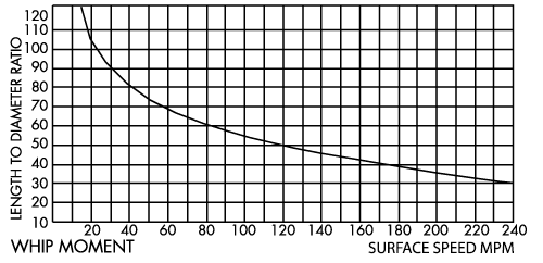
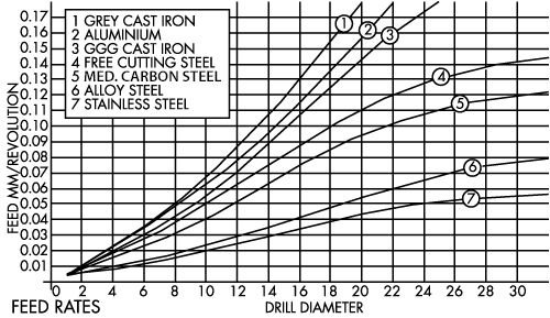
Cutting Parameters
Gun drills operate at relatively high cutting speeds with low feeds per revolution. Approximate starting values are shown in the charts on this page.
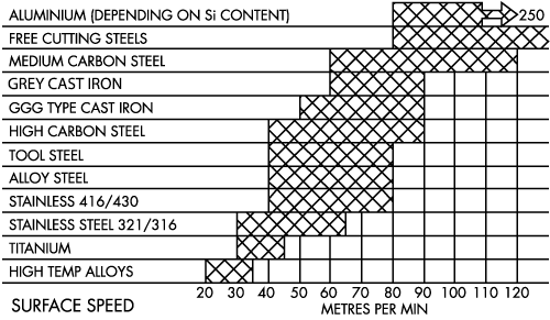
Feed rates are critical to chip formation. The values shown here may need to be adjusted for optimum results.
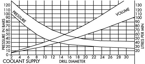
Reliable chip evacuation and good surface finish can only be ensured if sufficient coolant volume and pressure are available.
Pressure and volume vary according to length/diameter ratio.
Pressure and volume vary according to length/diameter ratio.
Chart shows maximum unsupported flute length.