Hammond & Company Ltd
Finway Road
Hemel Hempstead
Hertfordshire
HP2 7PT
United Kingdom
Tel +44 (0)1442 212211
Fax +44 (0)1442 252003
Email info@hammco.com
Finway Road
Hemel Hempstead
Hertfordshire
HP2 7PT
United Kingdom
Tel +44 (0)1442 212211
Fax +44 (0)1442 252003
Email info@hammco.com
- Ventec Design
- Manufacturing Spec
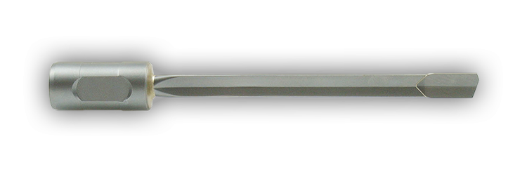
Ventec Drills
The problems of twist drilling deep holes are well known in the engineering industry. Drill wander, poor size control and surface finish, flank wear, binding and breakage are occupational hazards. The operation can be slow and inaccurate in the extreme.
An alternative is the use of Ventec drills which are designed to bring the benefits of gun drilling technology to conventional machine tools. Now for a relatively small outlay, it is possible to equip your machine shop with a system that provides a deep hole drilling capability, which in terms of speed and accuracy, equates favourably with gun drilling.
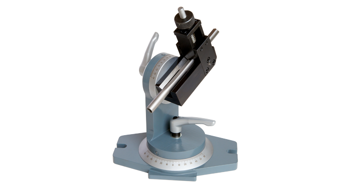
In operation the tool must be supported in a short pilot hole before drilling commences. Thereafter, penetration is continuous and depth to diameter ratios of up to 100:1 are achievable. The cutting forces created by the offset tip geometry act upon the carbide bearing pads, burnishing the workpiece and achieving fine surface finish and size control. It is this accuracy of dimensional control which is responsible for the excellent concentricity achieved by a Ventec drill. It has literally nowhere to go but forward.
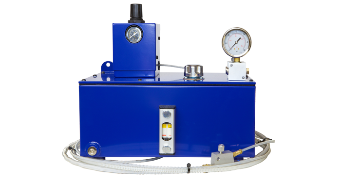
Spraymist
The HA3000 Spraymist units can be quickly fitted to most machine tools to give a deep hole drilling capability; they are portable and require only to be connected to the factory compressed air supply. The Ventec drilling system using a Spraymist unit works in the following way. A 3:1 air driven pump situated inside the Spraymist unit pressurises a 10% solution of water and Ventec cutting oil. This fluid is atomised by the compressed air at an adjustable sprayjet head and delivers the resulting mist mixture into the toolholder and through the Ventec drill. At the cutting face the mist mixture expands as it exits the hole in the carbide tip producing a refrigerating effect. The heat from the cutting process evaporates the water content of the mist leaving high lubricity oil to lubricate the burnishing pads of the cutting tip. The compressed air ejects the chips back along the drill flute and out of the hole.
The incoming air pressure should be 5,5-8,5 Bar (80-125psi). The coolant pressure should be set 3-5 Bar (45-75psi) above this pressure. The mist flow should be adjusted until a light mist is visible at the commencement of drilling. During the drilling cycle a trickle of fluid should just be noticeable returning along the drill shank and slightly wetting the face of the workpiece. To achieve optimum results the Ventec cutting oil mixing instructions must be followed exactly.
For full set up instructions see our video below.
We also offer a range of standard and custom built Coolant Fed Toolholders. For further information, please see our accessories.
accessories.
Spraymist/Ventec Instructional Video
Ordering Information
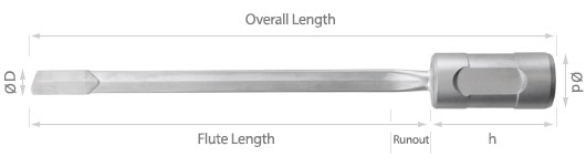
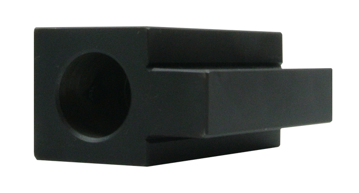
Please specify the drill diameter and flute length. The flute length should equal the hole depth plus 2 x diameter. This allows for re-grinding. If holes are deeper than 30 diameters they should be drilled in 30:1 stages. The driver size will be fitted according to the chart below.
For full ordering details required see Product Codes. Product Codes.
↓↓ Typewriter text for FOURTH sliding image ↓↓
| Driver Styles | Ref | Tip Diameter | Ød | h | Overall Length
|
|
|---|---|---|---|---|---|---|
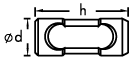 |
VT1 | CA | Ø5.0 - 11.73 | Ø16 | 40 | Flute Length + 50.0 |
| VT2 | CB | Ø11.74 - 21.18 | Ø25 | 50 | Flute Length + 65.0 | |
| VT3 | CC | Ø21.19 - 40.50 | Ø35 | 60 | Flute Length + 80.0 |
Text Block E
| Material | Surface Speed Metres |
Feed /Rev Ø6.0 |
Feed /Rev Ø8.0 |
Feed /Rev Ø10.0 |
Feed /Rev Ø15.0 |
Feed /Rev Ø20.0 |
Feed /Rev Ø30.0 |
|---|---|---|---|---|---|---|---|
| High Temp Alloys | 18 | 0.010 | 0.012 | 0.015 | 0.020 | 0.025 | 0.030 |
| Stainless Steel Alloys | 30 | 0.015 | 0.020 | 0.025 | 0.035 | 0.040 | 0.040 |
| High Carbon Steel | 38 | 0.015 | 0.020 | 0.030 | 0.040 | 0.050 | 0.050 |
| Medium Carbon Steel | 45 | 0.020 | 0.030 | 0.040 | 0.050 | 0.060 | 0.060 |
| Low Carbon Steel | 55 | 0.020 | 0.030 | 0.040 | 0.060 | 0.075 | 0.075 |
| Cast Iron | 35 | 0.040 | 0.060 | 0.100 | 0.130 | 0.150 | 0.180 |
| Free Cuttin Alluminium | 75 | 0.040 | 0.060 | 0.100 | 0.130 | 0.150 | 0.180 |
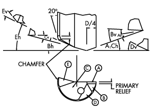
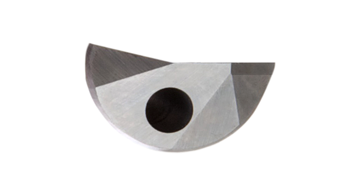
| Clamping Method |
|
|
||
|---|---|---|---|---|
| Face | Horiz | Vert | Horiz | Vert |
| A | +20° | +15° | +22° | +13° |
| B | +19.5° | +20° | +21.5° | +18° |
| C | -15° | +15° | -13° | +16° |
| D | 0° | +25° | 0° | +25° |
| E | -18° | -14° | -20° | -12° |
| Good surface finish required on faces A, C and Chamfer. | ||||
| DRILL DIA. |
PRIMARY RELIEF |
CHAMFER AT 20° |
|---|---|---|
| Ø5-Ø12 | 0.4 - 0.6 | 0.4 - 0.6 |
| Ø12-Ø25 | 0.6 - 0.8 | 0.6 - 0.8 |
| Ø25-Ø40 | 0.8 - 1.2 | 0.8 - 1.2 |